
Electricity & Magnetism
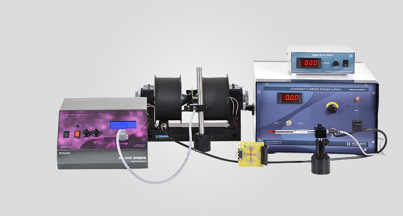
Holmarc's Hall Effect apparatus (Model no: HO-ED-EM-06) is designed with state of the art modules and components. Digital display is used for all value read outs. Electromagnets, gauss meter, power supply, etc. are designed and made as separate modules for students to understand the apparatus and the principles involved easily. Safety is given due consideration in the design of the apparatus
The system consists of two cartridges, each of which is equipped with 'p' and 'n' doped germanium crystal .The cartridges can be plugged easily and safely into the D connector system. The Hall Effect set up provides all operating parameters for the samples and displays the Hall voltage, sample current as well as the sample temperature. The doped Germanium samples are used to measure the Hall-voltage as a function of the sample current, the magnetic flux density and the sample temperature.
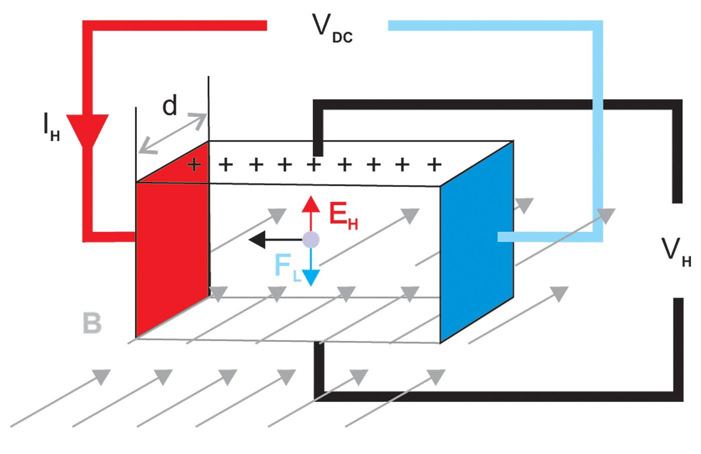
The Hall voltage is caused by the deflection of the moving charge carriers in the magnetic field due to the Lorentz force, of which, direction can be predicted by the right hand rule. The sign of the Hall coefficient is determined by the polarity of the charge carriers: a negative sign implies carriers with a negative charge ("normal Hall effect"), and a positive sign indicates carriers with a positive charge ("anomalous Hall effect"). The Hall coefficient depends on the material and the temperature.
Experiment
Measurement of Hall voltage as a function of
a. Magnetic flux density
Introduce the gauss meter probe between the poles of electromagnet. Change the current from zero up to its maximum value and from maximum to zero. Note the corresponding field strength from gauss meter at different intervals. Plot a graph Magnetic field Vs Current.
b. Sample temperature
Electrons in a semiconductor only become available for conduction when they acquire enough thermal energy to reach a conduction state; this makes the carrier concentration highly dependent on temperature.
c. Sample current
Connect the sample control probe to Hall Effect Control and turn on the Hall Effect set up. Vary the sample current from zero up to its maximum value in equal intervals. Note the corresponding Hall voltage readings. Plot the graph, Hall voltage as a function of the sample current.
Determination of density and mobility of charge carriers
We get Carrier Density from the equation,
n = [ 1 / ( RH e ) ] c m3
We get Carrier Mobility from the equation,
µ = RH . σ c m2 Volt-1 sec-1
where σ is the conductivity of material
Determination of Hall coefficient of semi conductor crystals
The Hall voltage VH is caused by the deflection of the moving charge carriers in the magnetic field due to the Lorentz force, whose direction may predicted by the right hand rule. The factor 1 / ( ne ) is called Hall coefficient RH.
RH = ( VH / B ) x ( d/IH ) c m3 Coulomb-1
B - Magnetic flux density
IH - Current through the semi conductor
d - Thickness of the conductor
n - Concentration of charge carriers
Scope of Supply

Model No: ED-EM-06-HECU
Current : 0 - 10 mA
Voltage : 0 - 200 mV
Display : 20 x 4 Alpha Numeric LCD
Quantity : 1 no.

Model No: ED-EM-06-SHRB
Material : Aluminum alloy
Finish : Black Anodized
Quantity : 1 no.

Model No: ED-EM-06-GPHM
Material : Aluminum alloy
Finish : Black Anodized
Quantity : 1 no.

Model No: ED-EM-06-DGM
Range : 0 - 20 K Gauss
Transducer : In As
Quantity : 1 no.

Model No: ED-EM-06-HEC
Material : n and p type lightly
doped Germanium (Ge)
Quantity : 1 no. each

Model No: ED-EM-06-EM
Max magnetic field : 5K Gauss
(at 20mm pole space)
Quantity : 1 no.

Model No: ED-EM-06-CCPS
Output Current : 0 - 3.5 A
Quantity : 1 no.
Connecting Cables
Instruction Manual
Established in 1993, Holmarc Opto-Mechatronics Ltd manufactures variety of scientific and engineering instruments for research, industry and education.
ISO 9001:2015 Made in INDIA
CIN : L33125KL1993PLC006984
GST No : 32AAACH9492C1ZQ
Navigation
Get in Touch
B.7., H.M.T. Industrial Estate
H.M.T. P.O, Kalamassery, Kochi
Kerala, India - 683 503
+91 920-719-7772 / 6 / 1
sales@holmarc.com
Mon - Sat : 9 am to 5 pm
Investor Zone # Online Dispute Resolution
 Print
Print